Since the post I recently put up on pneumatic controls (actually even before I did that), people occasionally ask me if there are resources out there that would help them better understand pneumatic controls. Even though the industry is moving to direct digital control as “business as usual”, if you are working in existing buildings, you will still find yourself confronted with pneumatic control technology. As a matter of fact, we just ran into a bunch of it during two field classes in the Existing Building Commissioning Workshop Series that I do with Ryan Stroupe at the Pacific Energy Center (see page two of the linked brochure if you are interested).
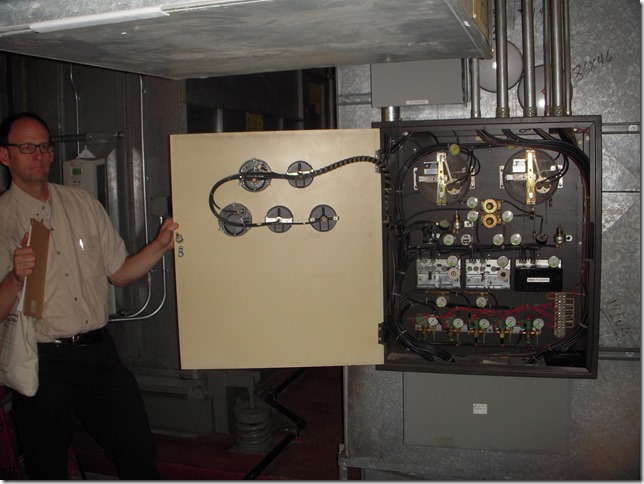
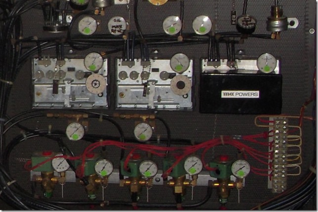
Here is a picture of a pneumatic control panel that is currently operating a system in Post Montgomery Center, a large high-rise in downtown San Francisco.
Erik Carlson, chief engineer for the facility, currently is working through the building and upgrading panels like this to DDC. But meanwhile, the operating team needs to keep the existing pneumatics in top form to maintain their LEED Gold status.
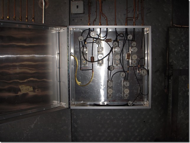
Across the Bay on the Berkeley campus, we ran into this pneumatic control panel which had been retained and piped through manual valves to back-up the retrofitted DDC control system serving the facility.
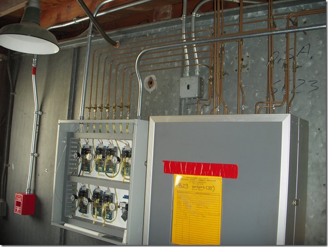
In this picture, you can see the pneumatic lines from the old control panel coming together through small, manual, isolation valves with the pneumatic lines from the electro-pneumatic circuit boards in the panel to the left (the valves are the small “T” shaped devices right above the panel to the left and in the lines above the panel on the right side, which is the pneumatic control panel in the picture above with the door closed).
Here is a close-up of the circuit boards in the panel to the left in the picture above.
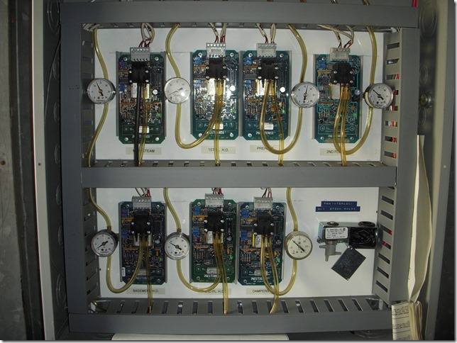
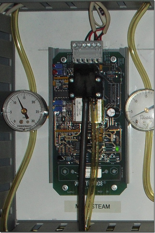
Basically, the boards respond to signals from the DDC control system to pulse air into or out of the line to the device they control. In the close-up of a typical board below, you can see the main air (nominal 25 psig supply air) coming into the board via the black tube and connecting to a manifold.
Two small solenoid valves (the shiny cylinders mounted on the black cube, which is the manifold) are pulsed by signals from the DDC system.
Pulsing one valve causes it to open and allow main air to flow into the output line (the yellowish tube with the gauge in it). Pulsing the other one allows it to bleed air out of the output line. These short, digital (on-off) signals work together to create the analog (continuously variable) air pressure output from the system that is used to position the final control element, which in this case, is a steam valve.
The bottom line is that to work on existing buildings (both now and for the foreseeable future near as I can tell) you probably need to have a working knowledge of pneumatic controls and some resources.
Unfortunately, a lot of the really great resources I had available to me when I was learning this stuff are no longer readily available. That’s because many of them were mentors who have retired, or in some cases, passed on. Others are printed materials that seem to have been supplanted by new information on the new technologies.
So, in an effort to honor the knowledge that was shared with me by the people, and to make the printed information I have available for others, I decided to scan some of my more useful resources and post them on my Google Drive so you can access them if you would like.
This is likely a violation of some sort of copy-right law, and if someone from one of the companies whose literature I have scanned contacts me and tells me to “cease and desist” with my effort, I will have to pull them back off. But I suspect that will not happen since much of this is from the 1960’s and 1970’s and most people consider the information it contains to be obsolete.
In fact, when I contacted one of the majors a while back to see if they would allow us to post their damper and valve sizing engineering bulletins as .pdfs on the California Commissioning Collaborative web site (I was with PECI back then) they not only said yes, the guy I was talking to asked me to forward copies to him too since they sounded really useful and he could no longer find the originals.
I still had mine because I kept my application engineering manuals from when I had worked for them. In the interim, the company had been sold several times and the various documentation and engineering resources were “cleaned up and made current” by the new owners, I guess.
Having said all of that, what follows is a listing of the documents I have put up along with a link to them and a description of what they are about and why I think they are useful. There is also a link to the folder containing them in the resource links on the home page of the blog.
The Honeywell Gray Manual
This is the one resource on the list that is not on my Google Drive. That is because you can download it from another location on the web. I link to it and discuss the “Gray Manual” in a previous post on the topic. The bottom line is that it contains useful information on a number of aspects of HVAC including chapters on all of the common control technologies, information on HVAC fundamentals, psychrometrics, and common HVAC system types, all presented in a very straightforward, understandable manner. It’s a great way for somebody new to the industry to gain an introduction to it and a valuable resource for someone who has been in it for a while and needs a “refresher” on a particular topic.
Johnson Controls (JCI) Fundamentals of Pneumatic Control
To be honest, one of the things I like the most about this particular document is more nostalgic than technical, that being the neatly printed signature and date of Phil Sutherlin across the top of the first page.
That’s pretty much how Phil printed all of the time, be it on a drawing that was going out the door or on the sketches and illustrations he made to help me learn things when I asked him questions.
As a young engineer, I strove to emulate it as well as and the free hand drawing style he used to lay out systems during schematics and design development. I actually got kind of good at it, and one of the things that bugs me about where technology has taken me is that since I type and click more and print and draw on paper less, I have lost a bit of that.
But I’m sidetracking a bit here. Nostalgia aside, the value of this particular document is that it contains a lot of very practical information about control theory (meaning that it applies to any control technology) as well as how that theory is implemented in a pneumatic instrument.
JCI Pneumatic Controls O&M Manual
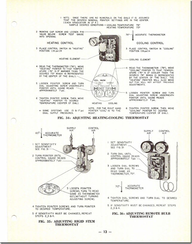
Some of the information in this document is similar to the Pneumatic Fundamentals documents. But the focus is more towards helping operators understand how to adjust and maintain the instruments.
There is even a section on replacement parts. Believe I t or not, we used to actually fix technology when it broke instead of throwing it away in a landfill and buying a new one. Perhaps a little lesson in sustainable operations there for us today.
MCC Powers Fundamentals of Pneumatic Controls
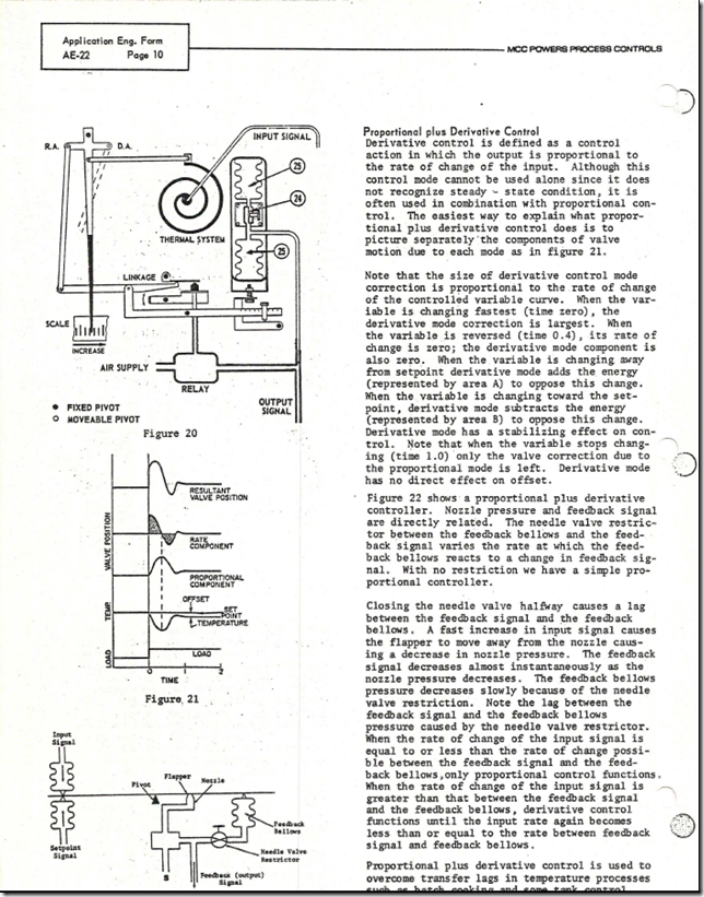
MCC Powers is now Siemens after going through a number of other owners in the process. Their Engineering bulletin on pneumatic controls fundamentals is a nice complement to the information in the JCI Document. While the JCI document includes some diagrams and a lot of pictures of the hardware, the MCC Powers document includes a lot of diagrams with explanations that illustrate how mechanical systems of diaphragms, levers, and springs were used to accomplish control processes like proportional control or floating control or PID.
Now, of course, we do all of this digitally with math. But for me at least, seeing and understanding how a mechanical device would accomplish the function was key to understanding how things worked, both then and now.
I think that is true for a lot of people actually because the “float in a tank” analogy I use when I teach PID control really seems to connect the dots for a lot of folks. I know it did for me and it has its roots in some of the discussions in documents like this one.
MCC Powers and JCI Pneumatic Main Sizing Data
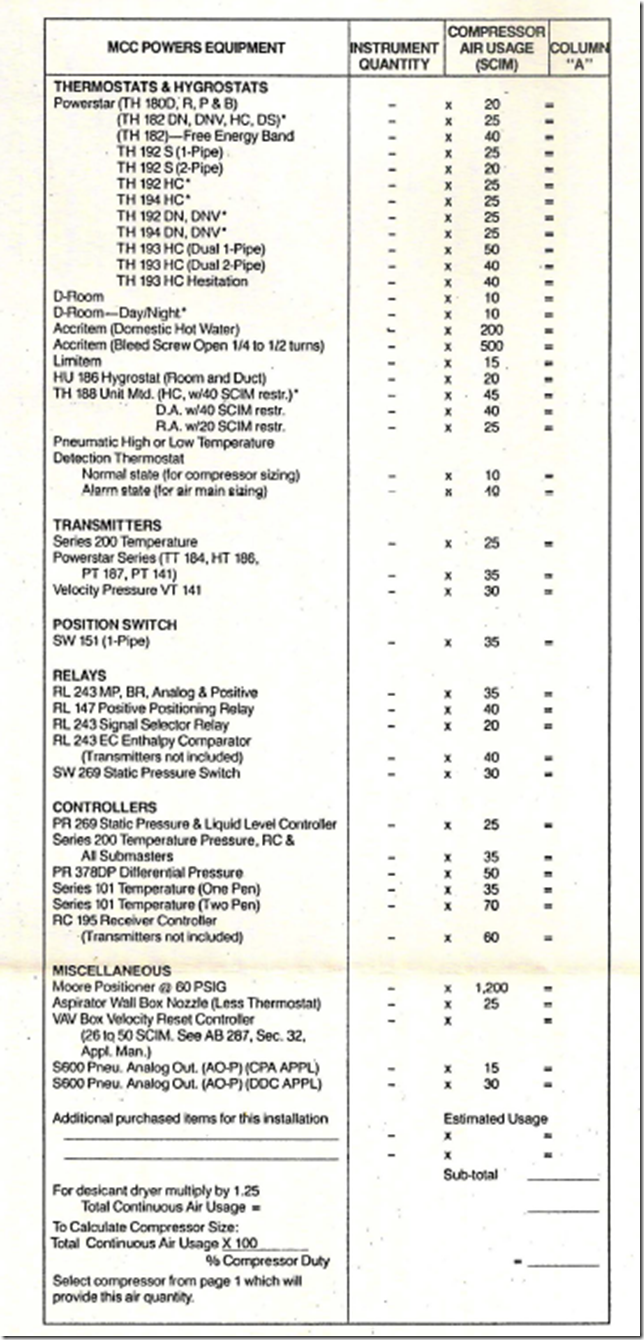
This document describes the process used to size the air mains along with related reference tables and sizing charts. One of the hardest things to find these days is some sort of documentation on the air consumption of various control devices. That can be useful information in an existing building commissioning process if you are trying to understand if a compressor is running more than it should due to leaks or if the demand from the control instrumentation is the cause.
Eventually, you can find out what you need to know, but you have to dig around a lot in the catalogs from various manufacturers. And often, the specific device you are looking for is no longer manufactured. Back when I did a lot of pneumatic control design, I had a table that listed most of the common devices from the MCC Powers product line along with their air consumption rate and I have scanned that table and included it in this set of documents.
I have found that it is reasonable to assume similar devices from other manufacturers use air at about the same rate in the general case, even though the specific values probably vary from manufacturer to manufacturer and device to device.
In addition, even thought pneumatic controls are receding from the scene, pneumatic actuation is alive and well. So having the ability to size air mains and compressors is still quite handy out there in the field.
One note with regard to sizing systems for actuators; when I first got into this, I was puzzled about why the table above did not include consumption rates for actuators. It finally dawned on me that it was because unlike a pneumatic controller ,which constantly bleeds air to operate (the link takes you to some slides that illustrate this), pneumatic actuators only use air when they move. And the volume they require to go full stroke is basically the diameter of the actuator cylinder times its stroke.
That means if you had a system that was only serving devices like actuators, then the size of the compressor and mains is more a function of how many actuators you think might move concurrently and how quickly you need them to move. That means that you can often get away with a smaller compressor, especially if you complement it with a large storage tank, which can act as a sort of pneumatic flywheel.
MCC Powers RC 195 Receiver Controller System
For me at least, one of the best ways to understand something is to immerse myself in the details of how it works. This document will allow you to do that for an RC 195, which is the MCC Powers (now Siemens) receiver controller. This device is still available and in use out there In fact, the controllers in the Post Montgomery panel at the beginning of this post are RC 195s.
The controllers in the UC Berkeley Facility control panel are similar devices but manufactured by Honeywell.
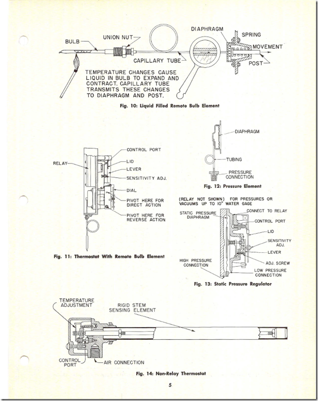
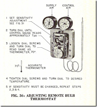
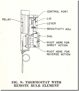
The fundamental difference between a receiver controller and a controller that has the sensor built into it, like the remote bulb controller illustrated below, is that instead of using a sensing element that measured a specific parameter, like temperature, which was an integral part of the controller, receiver controllers were set up to use a 3-15 psig pneumatic input.
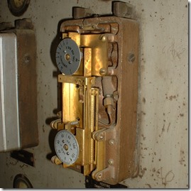
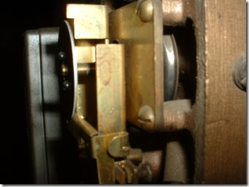
In the pictures, the upper row are taken from the JCI Operating Manual and show the parts and a cross section of a controller very similar to the one in the photographs below. In the photo at the lower left, you can just see the bellows that is part of the temperature sensing assembly (the silver cap shape behind the plate with screws) that shows up connected to the thermal sensor in the illustration above.
Returning to the receiver controller discussion, by using a generic 3-15 psi pneumatic input, receiver controllers could be interfaced with pneumatic transmitters that were designed to measure a number of different HVAC parameters like temperature or humidity or pressure.
The transmitters generated a signal that varied from 3-15 psi as the parameter they measured varied over a given span like 0-100°F. They are identical in concept to the 4-20 ma, 1-5 vdc, and 2-10 vdc transmitters we use today with DDC systems. They just used air pressure to transmit the information instead of electrons.
If you understand one technology, you can easily understand the other, which is a topic I discuss in an article I wrote for HPAC magazine a while back called Analog Lessons for a Digital World, along with other things I learned working on pneumatic controls but apply every day while working with DDC controls. My bet is the “cross training” works the other way too; i.e. if you understand DDC control fundamentals, you can readily transition to pneumatics once you learn the jargon and hardware.
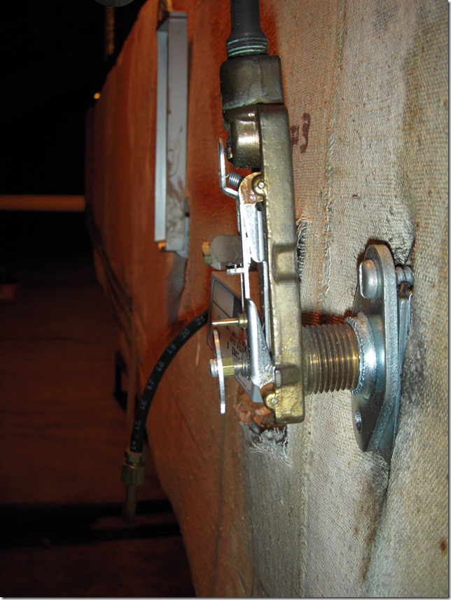
Here is a picture of a one-pipe temperature transmitter that is piped to one of the controllers in the panel at UC Berkeley, illustrated at the beginning of the post.
The generic input capability meant that only one controller design was required and you adapted it to the HVAC process by virtue of the transmitter you selected.
Bottom line is that the RC195 documentation will allow you to get into the details of how one works and how to use it. In addition, it has been my experience that once you understand a specific device, the knowledge is easily transferred to similar technologies from other manufacturers.
Fisher Process Grade Pneumatic Controllers and MCC Powers Series 200
If you really want to see how a remote bulb type controller works, the product bulletins for these process grade controllers will give you a pretty good picture of that. Incidentally, the MCC Powers Series 200 controller is the controller that shows up in the pictures in the photo gallery in the post titled Retrocommissioning Findings: Make Up Air Handling System Simultaneous Heating and Cooling – The Clues – #2 – The Controls May be Pneumatic.
The instructions are hard to find; I lost my copy when I moved to Portland and the box the the binder with all of my MCC Powers manuals was lost. The copy I ‘m sharing here was graciously shared with me by Adam Lebavitz of M&M Control Service Inc. M&M now owns the remaining stock and manufacturing rights to the Series 200, so if you are looking for parts or service on this type of equipment, they are the folks to talk to.
JCI Damper Engineering
One of the advantages of going back into your files and looking for something is that sometimes, you discover something useful that you forgot you had. This is an example of that and comes from the JCI engineering manual that Phil gave me.
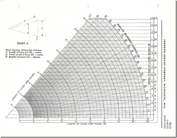
Among other things, this document contains actuating force and stroke data for a number of different actuator types, including a technical discussion of the topic and a really cool little nomograph that helps you figure out the relationship between lever arm, stroke and angular rotation for a given arrangement.
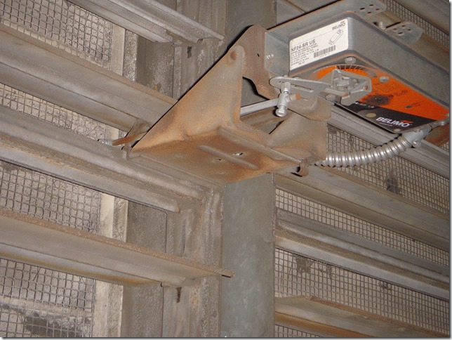
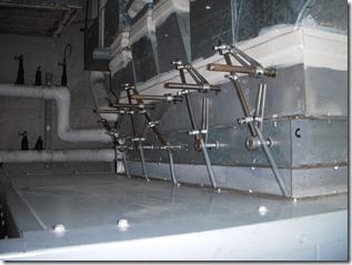
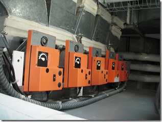
When I bring this topic up, some folks say its not very useful information given that the industry is moving to centerline drive actuators and eliminating the linkage systems between the actuator and the damper. Personally, I’m not so sure about that as illustrated by these recent field photographs.
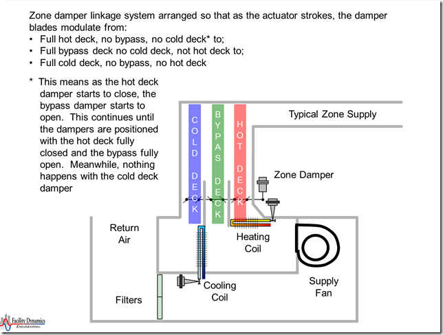
The upper photograph is an actuator serving one of a number of outdoor air damper sections in a large (200,000 cfm) economizer equipped AHU. The lower pictures are from a triple deck multizone unit. The actuators on the left control all three deck dampers through a menagerie of lever arms, springs, and shafts. Here is a system diagram of the unit which will help you understand.
Interesting study in kinematics if nothing else.
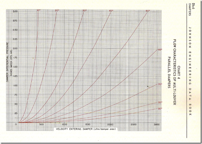
Another interesting thing is the damper performance curves included towards the end.
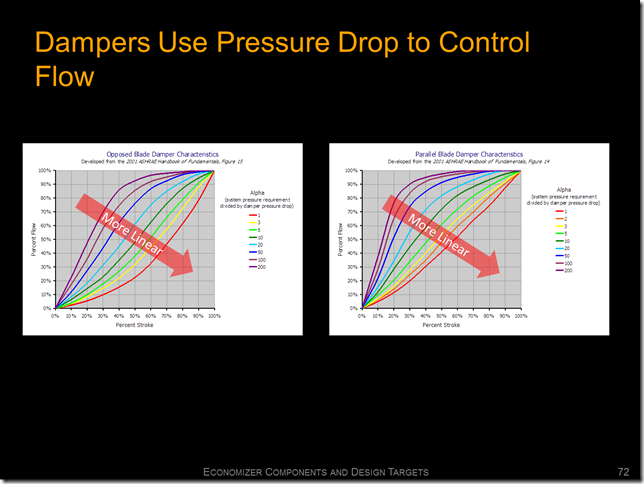
I haven’t tried it yet, but I suspect you could manipulate this data into a version of the damper performance data that shows linearity vs. pressure drop that can be found in a number of places like the Honeywell Gray Manual and the MCC Powers Damper Sizing Bulletin I link to in the resources on the blog’s home page.
Granted, the information in this document pertains to older models. But my bet is that geometric similarity and some engineering judgment would allow you to extrapolate this information to a current application. That can be particularly useful if you don’t have any other information to work from.
JCI Reference Information
This is one of those collections of useful facts and figures that are handy to have around. This particular documents includes things like:
- units conversion constants,
- basic HVAC and physics equations,
- a steam table,
- tables with the relationship between wet bulb, dry bulb, dew point, and relative humidity,
- velocity vs. velocity pressure tables,
- properties of things like glycol and other anti-freeze solutions,
- standard pneumatic control drawing symbols (well, the JCI standard anyway, which was a pretty good one actually and similar to the other manufacturers),
- design conditions for a number of places (bear in mind this is probably mid 1960’s data), and
- summary psychrometric process diagrams for typical HVAC processes.
The latter is one of the reasons I have included it since it is a quick way for someone new to the industry to start to understand what happens in some of our HVAC processes and correlate it with the psych chart. For example, here is the one for a cooling coil that is doing dehumidification and cooling.
Well, that’s it.
Hope this is useful to some of you. I know I have found the information to be useful over the course of my career, including the current time frame.

David Sellers
Senior Engineer – Facility Dynamics Engineering



Great stuff David. Reminds me of some of the buildings I worked at in the 80’s and 90’s.
Dave Mason
Sent from my iPad
Thanks Dave; a bit of technical nostalgia.
David
(I swear everytime I get an e-mail from you and see your signature line, World in Changes starts running around in my head.)
Thank you for sharing the pneumatic resources and for taking the time to share your knowledge as always! The old literature seems to explain things in a much more digestible manner so these are very much appreciated.
Thanks Austin. Glad the information was helpful. I totally agree with the comment about old literature. Along those lines, I have always found Willis Carrier’s original book “Modern Air Conditioning, Heating, and Ventilation” (1940; I have a 1950 edition) (that I still refer to) to be very approachable. In it he specifically states that one of the goals in writing it was so that it was not only useful to engineers, but also to the folks out there trying to operate and otherwise work with the systems.
The same is true for Joseph Olivieri’ book “How to Design Heating-Cooling Comfort Systems. You can still find used copies around on Amazon and such, so if the style of the pneumatic literature appeals to you, you might find these other books to be worth having.
Thanks for taking the time to comment and visit the blog,
Take care,
David